게임 개발을 공부하면서 언리얼 엔진만을 다룬다고 하더라도 DirectX에서 구현하는 것처럼 정점(Vertex)를 이용한 Texture 그리기, Mesh 다루기 등의 개념들을 잘 알고 있어야 한다.
따라서 이번에는 정점을 다루는 Vertex 클래스를 생성한 뒤, 정점으로만 그린 Cube를 게임에 배치하는 내용을 구현해보았다.
추후에는 이러한 내용들을 이용하여 툴바에 추가해두었던 커스텀 버튼(LoadMesh)의 기능으로 어떤 Mesh를 선택할 때 Mesh의 정보를 읽어와 Color를 변경하거나 Mesh 파일을 따로 저장하는 등의 기능을 구현할것이다.
💻 Draw Vertex 클래스
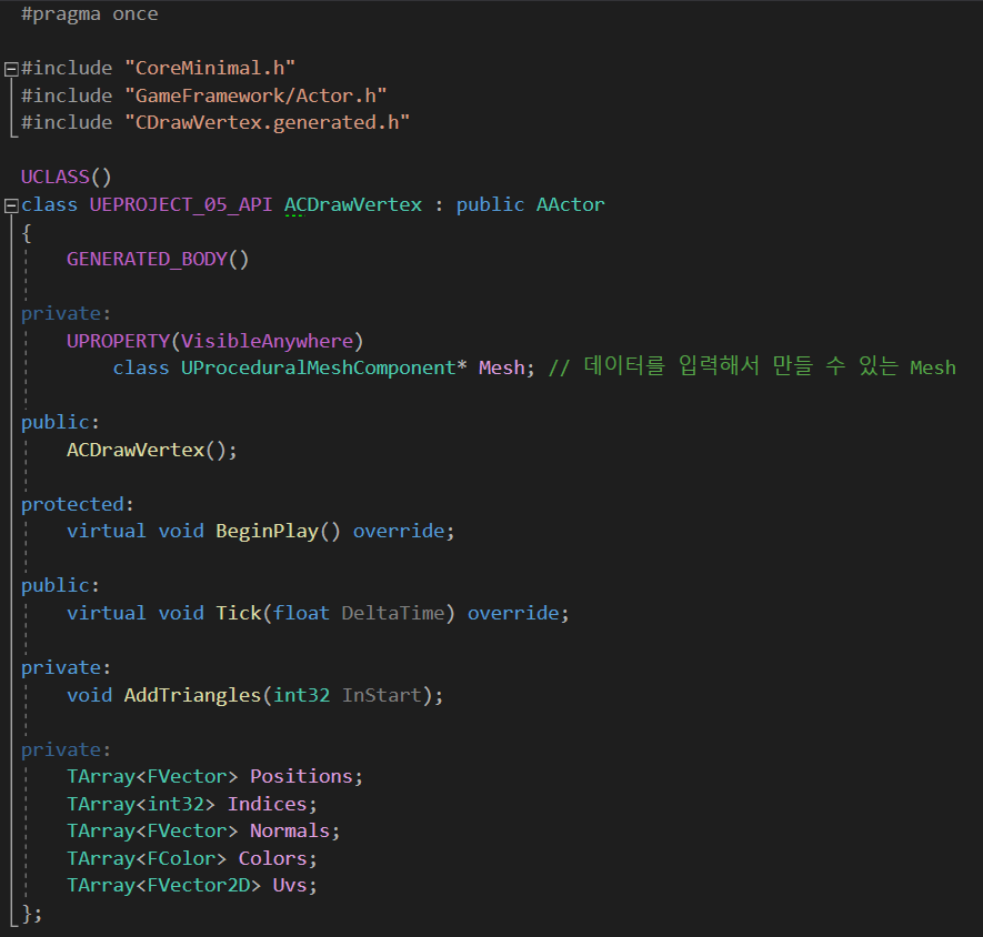
먼저, 정점 데이터를 가지고 Mesh를 직접 그릴 수 있는 DrawVertex 클래스를 생성하였다.
UProceduralMeshComponent는 데이터를 입력해서 직접 형태를 만들 수 있는 Mesh 객체이다.
그밖에 정점의 데이터인 Positions, Indices, Normals, Colors, Uvs 변수들을 TArray로 각각 선언해주었다.
💡 Position 추가하기 + Colors, Normals

먼저 ProceduralMeshComponent를 초기화한 뒤, Vertex를 그리기 위해 Positions와 Colors, Normals를 추가하였고
AddTriangles 함수를 통해 삼각형을 그릴 때 사용되는 순서별 Index들을 추가하였다.
가로,세로 1을 길이로 두는 사각형을 그리기 위해, 중앙점 P를 (0.5f, 0.5f, 0.5f) 로 초기화하였고, 언리얼과 DirectX는 모두 정점을 그릴 때 반시계방향으로 그려야 한다는 것을 주의하였다.
보기 쉽도록 Front와 Back, Top, Bottom, Left, Right를 중괄호로 구분하여 코드를 작성하였다.
Front를 먼저 보면 왼쪽하단, 왼쪽 상단, 오른쪽 하단, 오른쪽 상단 순으로 정점들을 저장하였고
각 면들의 색상을 다르게 지정하며 Colors에 색상값을 추가하였다.

내가 그린 정육면체의 좌표를 그림으로 보자면 위와 같다.
중앙점 P가 존재할 때 각각의 왼쪽, 오른쪽, 상단, 하단, 앞, 뒤의 정점 좌표는 위와 같이 나온다.
💡 Indices 추가하기 (AddTriangles 함수)
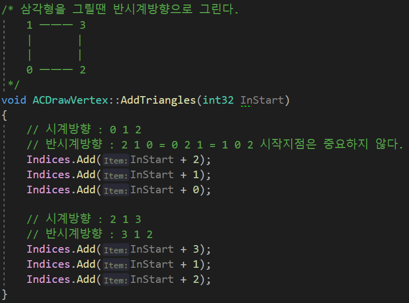
AddTriangles 함수는 시작점 하나를 받으면 그로부터 Index 6개를 추가하여 한 면을 그리기 때문에 Front, Back, Top ,,, 같은 각각의 면을 그릴때 한번씩만 호출하였다.
또한 한 면을 그릴 때 사용되는 정점이 4개 이므로, AddTriangles(0), AddTriangles(4), AddTriangles(8), AddTriangles(12), ... , AddTriangles(20) 까지 4 간격으로 함수를 호출하였다.
💡 UV 추가하기

모든 면의 Position, Color, Normal, Index를 다 추가하고 난 후, Uvs는 모든면이 같은 순서로 그려지기 때문에 한번에 추가하였다.

마침내 정점의 정보가 모두 갖춰졌으니 생성해두었던 UProceduralMeshComponent 객체인 Mesh의 CreateMeshSection 함수를 이용해 Mesh를 생성하였다.
매개변수로 각 정점 데이터를 넘겨주었고, 정점간의 길이가 1 인 작은 크기이므로, Scale을 100씩 늘려 출력해주었다.
DrawVertex.cpp의 전체코드는 게시글의 맨 아래 삽입하였다.

이후 C++ 클래스인 DrawVertex를 기반으로 블루프린트 BP_CDrawVertex를 생성하였고,
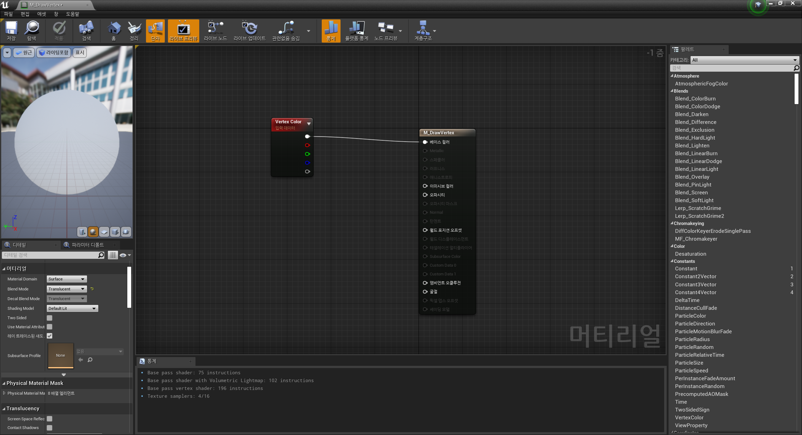
Vertex Color 를 입력데이터로 받은 머티리얼을 블루프린트에 설정하면 위와 같이 각 면마다 설정했던 색상값들이 정상적으로 출력되는것을 확인할 수 있었다.

또한 정점의 UV 정보를 TexCoord로 읽어와 Texture Sample을 베이스컬러로 함께 출력한다면

위와 같이 Texture와 Color 정보가 혼합되어 잘 출력되는것을 볼 수 있었다.
💡 정점 수정하기 (Vertex Update)
한번 만들어진 정점을 잘 수정하진 않지만, 만약 수정이 필요한 경우에는 Mesh의 UpdateMeshSection 함수를 이용하여 정점을 Update 시켜줄 수 있다.

UpdateMeshSection 함수의 매개변수는 CreateMeshSection 함수와 거의 동일하지만, Indices와 true 매개변수 두 개만 제외시키면 된다.
Indices는 처음 Mesh를 생성한 뒤로 변화하지 않기 때문에 Update 목록에서 제외되고, 마지막 true 변수는 Create Collision에 관련된 변수이므로 지워준다.
Tick 함수를 1초마다 실행되도록 PrimaryActorTick.TickInterval = 1.0f; 을 설정해두었으니 1초마다 Mesh의 색상을 랜덤으로 변경시키는 코드를 작성해보았다.
 |
 |
 |
 |
 |
프로그램 실행 결과, 1초마다 Mesh의 정점이 정상적으로 Update 되며 색상이 랜덤 변경됨을 확인할 수 있었다.
📄 DrawVertex.cpp 전체 코드
#include "CDrawVertex.h"
#include "Global.h"
#include "ProceduralMeshComponent.h"

ACDrawVertex::ACDrawVertex()
{
	PrimaryActorTick.bCanEverTick = true;
	PrimaryActorTick.TickInterval = 1.0f;

	CHelpers::CreateComponent<UProceduralMeshComponent>(this, &Mesh, "Mesh");

	// 중앙을 0으로 잡기 위함
	FVector p = FVector(0.5f, 0.5f, 0.5f);

	// 정점을 그리는 방향: 반시계
	// Front
	{
		Positions.Add(FVector(-p.X, -p.Y, -p.Z)); // 0
		Positions.Add(FVector(-p.X, -p.Y, +p.Z)); // 1
		Positions.Add(FVector(-p.X, +p.Y, -p.Z)); // 2
		Positions.Add(FVector(-p.X, +p.Y, +p.Z)); // 3

		for (int32 i = 0; i < 4; i++)
		{
			Colors.Add(FColor(128, 0, 0, 255));
			Normals.Add(FVector(-1, 0, 0));
		}
		AddTriangles(0);
	}

	// Back
	{
		Positions.Add(FVector(+p.X, +p.Y, -p.Z));
		Positions.Add(FVector(+p.X, +p.Y, +p.Z));
		Positions.Add(FVector(+p.X, -p.Y, -p.Z));
		Positions.Add(FVector(+p.X, -p.Y, +p.Z));

		for (int32 i = 0; i < 4; i++)
		{
			Colors.Add(FColor(0, 128, 0, 255));
			Normals.Add(FVector(+1, 0, 0));
		}
		AddTriangles(4);
	}

	// Top
	{
		Positions.Add(FVector(-p.X, -p.Y, +p.Z));
		Positions.Add(FVector(+p.X, -p.Y, +p.Z));
		Positions.Add(FVector(-p.X, +p.Y, +p.Z));
		Positions.Add(FVector(+p.X, +p.Y, +p.Z));

		for (int32 i = 0; i < 4; i++)
		{
			Colors.Add(FColor(0, 0, 128, 255));
			Normals.Add(FVector(0, 0, +1));
		}
		AddTriangles(8);
	}

	// Bottom
	{
		Positions.Add(FVector(-p.X, -p.Y, -p.Z));
		Positions.Add(FVector(-p.X, +p.Y, -p.Z));
		Positions.Add(FVector(+p.X, -p.Y, -p.Z));
		Positions.Add(FVector(+p.X, +p.Y, -p.Z));

		for (int32 i = 0; i < 4; i++)
		{
			Colors.Add(FColor(0, 128, 128, 255));
			Normals.Add(FVector(0, 0, -1));
		}
		AddTriangles(12);
	}

	// Left
	{
		Positions.Add(FVector(+p.X, -p.Y, -p.Z));
		Positions.Add(FVector(+p.X, -p.Y, +p.Z));
		Positions.Add(FVector(-p.X, -p.Y, -p.Z));
		Positions.Add(FVector(-p.X, -p.Y, +p.Z));

		for (int32 i = 0; i < 4; i++)
		{
			Colors.Add(FColor(128, 0, 128, 255));
			Normals.Add(FVector(0, -1, 0));
		}
		AddTriangles(16);
	}

	// Right
	{
		Positions.Add(FVector(-p.X, +p.Y, -p.Z));
		Positions.Add(FVector(-p.X, +p.Y, +p.Z));
		Positions.Add(FVector(+p.X, +p.Y, -p.Z));
		Positions.Add(FVector(+p.X, +p.Y, +p.Z));

		for (int32 i = 0; i < 4; i++)
		{
			Colors.Add(FColor(128, 128, 128, 255));
			Normals.Add(FVector(0, +1, 0));
		}
		AddTriangles(20);
	}

	/* Uvs는 공통
	0,0 ㅡㅡ 1,0
	|          |
	|          |
	|          |
	0,1 ㅡㅡ 1,1
	*/
	for(int32 i = 0; i < 6; i++) // 6 = Front, Back, Top, Bottom, Left, Right
	{
		Uvs.Add(FVector2D(0, 1));
		Uvs.Add(FVector2D(0, 0));
		Uvs.Add(FVector2D(1, 1));
		Uvs.Add(FVector2D(1, 0));
	}

	// Create Mesh
	Mesh->CreateMeshSection(0, Positions, Indices, Normals, Uvs, Colors, TArray<FProcMeshTangent>(), true);
	Mesh->SetRelativeScale3D(FVector(100));
}

void ACDrawVertex::BeginPlay()
{
	Super::BeginPlay();

}

void ACDrawVertex::Tick(float DeltaTime)
{
	Super::Tick(DeltaTime);

}

/* 삼각형을 그릴땐 반시계방향으로 그린다.
	1 ㅡㅡㅡ 3
	|       |
	|       |
	0 ㅡㅡㅡ 2
 */
void ACDrawVertex::AddTriangles(int32 InStart)
{
	// 시계방향 : 0 1 2
	// 반시계방향 : 2 1 0 = 0 2 1 = 1 0 2 시작지점은 중요하지 않다.
	Indices.Add(InStart + 2);
	Indices.Add(InStart + 1);
	Indices.Add(InStart + 0);

	// 시계방향 : 2 1 3
	// 반시계방향 : 3 1 2
	Indices.Add(InStart + 3);
	Indices.Add(InStart + 1);
	Indices.Add(InStart + 2);
}